Project
2 DOF Ball Gimbal
Full System Integration
Success! This captures the full operation of the gimbal with both pitch and roll axes actively stabilized. Mounted to its platform, the gimbal responds smoothly to disturbances, maintaining camera orientation with high precision. The synchronized control of both axes demonstrates the effectiveness of the full system integration. This marks a major milestone in validating the design’s stability, responsiveness, and readiness for real-world deployment.
Initial 3D-Printed Prototype
The first iteration of the gimbal design was fully 3D printed, allowing for cheap prototyping and initial testing of mechanical fit and function. However, the approach introduced key issues: surface interfaces lacked the precise tolerancing required for smooth motion, resulting in excessive friction between moving parts. Additionally, the 3D-printed material contributed significant weight, which negatively impacted the aircraft’s center of gravity. These limitations informed the transition to a lighter, more precisely manufactured carbon fiber assembly in the next design phase.
Testing the V1 Prototype
The video shows the partially assembled 3D-printed prototype, featuring a Teensy 4.0 microcontroller and an early version of the custom motor driver board. The test focuses on evaluating the roll and pitch axis functionality under manual input conditions. A potentiometer is used to generate analog control signals, allowing the user to command the gimbal's orientation interactively. This prototype test was a key step in validating basic motion response and identifying friction and balance issues in the initial design.
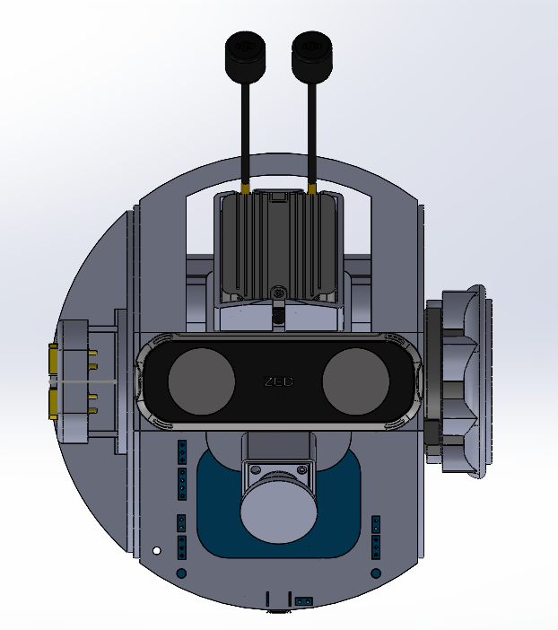
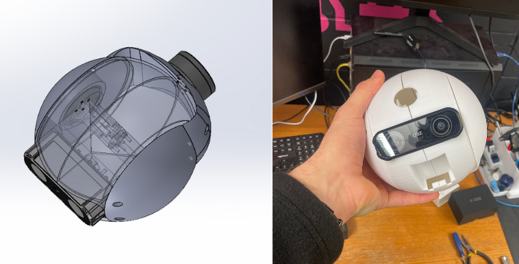
Final CAD Design
The V3 design features a robust assembly of flat water-jet-cut carbon fiber plates joined with box joints to maintain precise orientation during gluing. The front of the gimbal houses both the DJI FPV system and the Zed X Mini Depth Camera, securely mounted for forward-facing visibility. XT30 connectors on the left side provide external access for charging and powering the system, while the pitch-axis BLDC motor is mounted on the right using a PETG-CF 3D-printed bracket for added strength. Behind the central plate lies a custom 3-cell lithium-ion battery pack and BMS, strategically placed to counterbalance the off-axis sensor mass and ensure smooth motion.
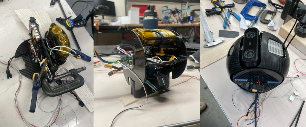
Assembly Process
The gimbal assembly process began with the integration of the camera, control electronics, and power system into the central housing. Each joint is glued and clamped sequentially, with paper shims used to ensure proper clearance between plates that require relative motion. In the final image, the carbon fiber skin is being fitted and trimmed; it was laid up in a single-piece donut-shaped 3D-printed mold, with cutouts aligned to preformed indentations in the mold for precise fitment.
A Look Inside
This video shows the complete mechatronic assembly of the gimbal, highlighting the integration of mechanical and electrical systems. A magnetic encoder is visible on the back of the roll axis, enabling precise feedback for closed-loop control, while a slip ring allows continuous signal transmission through the roll joint. The custom lithium-ion battery pack is also featured, acting as a counterweight to stabilize the pitch axis and reduce motor load.
Disturbance Test
This demonstrates the gimbal operating under field-oriented control (FOC) in closed-loop mode. In early open-loop tests, external disturbances caused the BLDC motor poles to slip, resulting in instability and lost positioning. By incorporating a magnetic encoder for feedback, the system can now actively track and correct the motor’s position in response to external forces. The video clearly shows the motor maintaining its commanded orientation despite physical disturbances, validating the effectiveness of the closed-loop control strategy.
Roll Axis Stabilization
This video showcases roll axis stabilization using real-time feedback from the onboard IMU. The gimbal maintains level orientation autonomously, demonstrating effective closed-loop control on a single axis. It also highlights the modularity of the system, as the gimbal operates entirely self-contained without any external data cables connected to the rear. This design enables quick integration and testing while simplifying mounting on different platforms.