Project
Field-Oriented Control Board
Final PCB Design
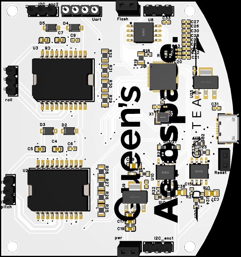
A rendering of the third and final PCB design, featuring a curved edge that sits flush against the gimbal's center plate, allowing the micro-USB port to protrude cleanly for easy external access. On the right side is the RP2040 microcontroller with its external flash memory positioned above it. Two dedicated I²C ports are broken out to interface with the magnetic encoders, which have fixed addresses and must be isolated on separate buses. On the left side of the board, the L6234 motor driver is visible alongside voltage dividers used to monitor phase current.
Testing the 'Bare Bones'
The first prototype of the gimbal control system, using an Arduino Nano and an L6234 motor driver on a hand-wired prototype board. A potentiometer supplies input, and the Arduino generates three 120-degree out-of-phase PWM signals to control the BLDC motor via duty cycle modulation. The motor’s jumpy and inconsistent response reveals the limitations of open-loop control and the electrical noise introduced by loosely arranged wiring. Unlike later designs with a proper PCB featuring a continuous ground plane, this early version lacked proper grounding and isolation, making it far more susceptible to noise and unstable behavior.
First PCB Shortcomings
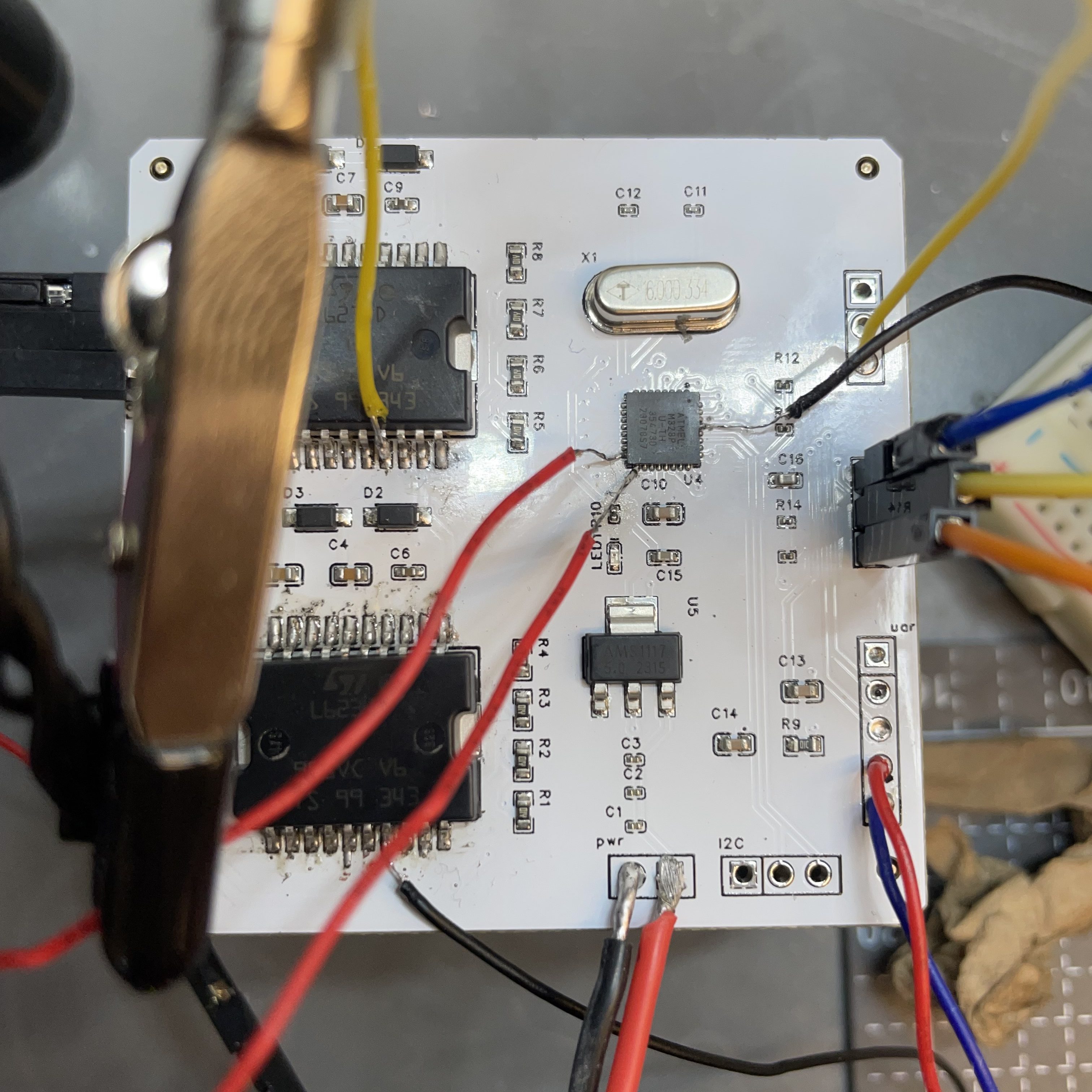
This image highlights the programming challenges encountered with the first PCB iteration. I initially assumed the ATmega328 microcontroller would come pre-flashed with a bootloader, but it did not, which prevented uploading Arduino sketches directly. To resolve this, I had to use a separate Arduino Uno to burn the bootloader onto the chip. Since I hadn’t anticipated this issue, I didn’t include an ICSP header in the design, forcing me to solder wires directly to the SMD pins, an error that made early development unnecessarily tedious.
Proof of PCB Design
The first custom PCB is shown controlling the speed of both gimbal motors. At this stage, the board operates in open-loop mode, simply receiving a PWM signal as input and mapping it to a motor speed by adjusting the duty cycles of the three-phase outputs per motor. It does not directly control angular velocity or respond to feedback; only the input PWM value determines the motor’s behavior. This lack of closed-loop feedback makes the system vulnerable to disturbances and limits its precision and stability.
Introducing Feedback
This video captures the initial attempt to incorporate feedback into the system using a slotted optical optocoupler as a basic encoder. If you watch closely, you can see noticeable choppiness in the motor's motion, which stems from the extremely low resolution of the optical encoder. The limited number of slots provided very coarse positional feedback, making smooth control difficult. While it marked a step toward closed-loop control, the resolution was insufficient for precise or stable gimbal operation.
PCB Mistakes
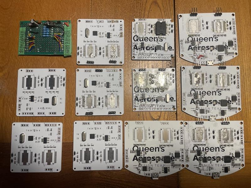
Learning PCB design and best practices was not a perfect process. This image displays the four PCB design iterations developed throughout the gimbal project. The first version was a basic prototype on perfboard, housing only a motor driver and filter for initial testing. The second design introduced a custom PCB but lacked programming breakouts, making firmware development cumbersome. The third iteration, using an ATmega328p, suffered from insufficient compute resources and lacked back-voltage protection, leading to frequent failures when misconnected. The final version integrated an RP2040, which provided ample processing power and reliable performance for running both motor and orientation control loops.
Field-Oriented Control
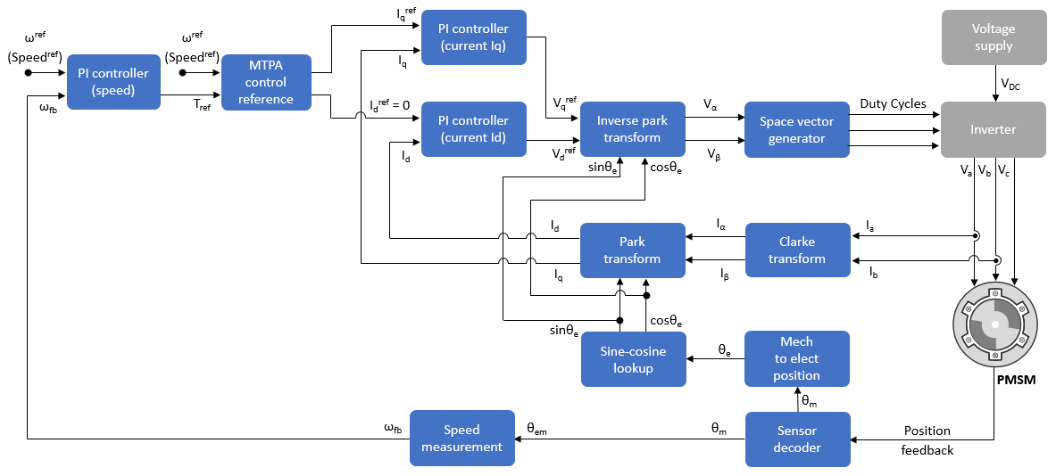
Field-Oriented Control (FOC) is an advanced motor control technique that precisely regulates torque and magnetic flux in brushless DC motors by transforming phase currents into a rotating reference frame. Unlike simpler control strategies, FOC uses real-time feedback, typically from encoders, to dynamically adjust current inputs, enabling highly responsive and efficient control. This method provides smooth and quiet motor operation, which is particularly valuable in gimbal systems where jitter and vibration can compromise camera stability. FOC also delivers high precision in positioning, making it ideal for maintaining accurate orientation in the presence of external disturbances. Additionally, it improves energy efficiency by applying only the necessary current, reducing power consumption and heat buildup, which are key benefits for compact, battery-powered UAV payloads. Overall, FOC enables gimbals to achieve superior performance in stabilization, accuracy, and operational reliability.
FOC in Action
A single BLDC motor running under a field-oriented control (FOC) loop, with a magnetic encoder mounted on top of the motor shaft for position feedback. The setup was used to validate the FOC implementation before full gimbal integration. As the motor spins, the encoder continuously reports angular position, allowing the controller to dynamically adjust phase currents and maintain smooth, precise motion.