Project
VTOL Design
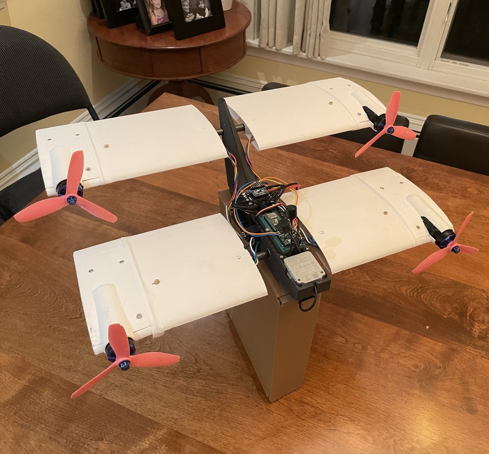
Full VTOL Assembly
The wings were 3D printed in lightweight PLA to minimize overall mass and reduce the impact on flight dynamics. This picture shows the fully assembled prototype with all major components integrated, including the printed wings mounted to the actuation system. The use of PLA kept the structure light while still providing enough rigidity for basic testing. This final assembly marked the transition from subsystem testing to full system integration.
The Hardware
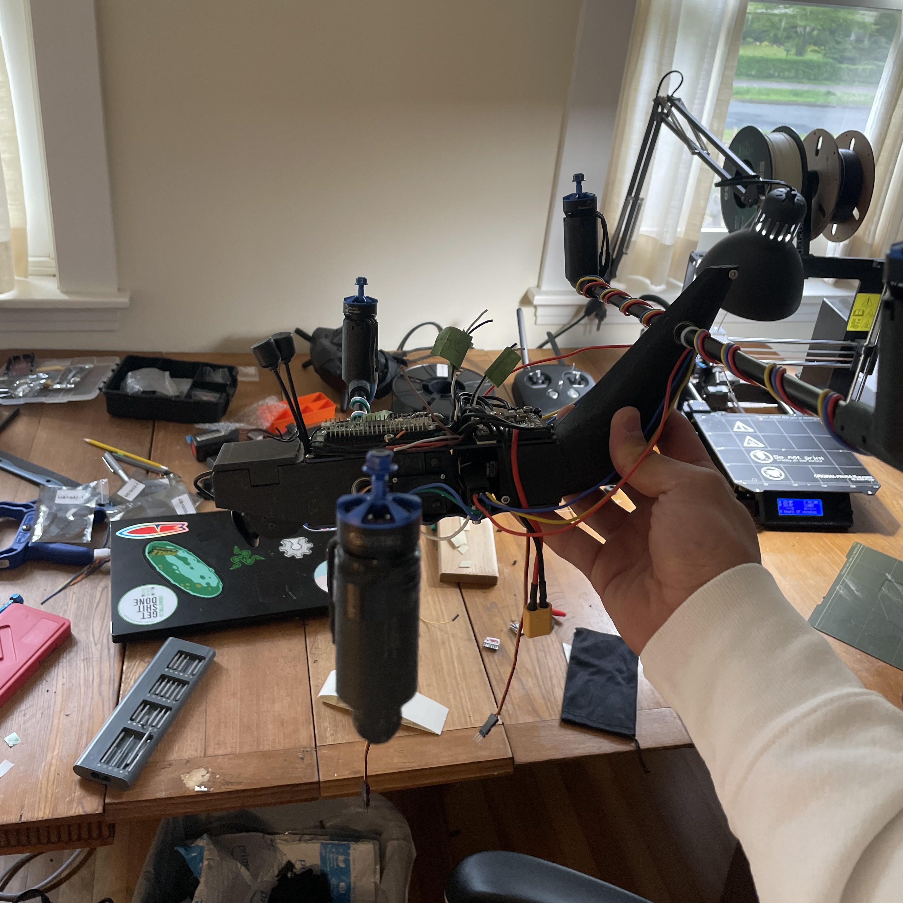
The partially assembled VTOL aircraft shows the carbon fiber frame and core components, with the wings not yet fully attached, exposing the internal structure including the front gearbox and rear belt-driven wing mechanism. The electrical system is centered around a Teensy 4.0 microcontroller, supported by a power distribution board for motors and servos. Key inputs like the IMU, GPS, and receiver feed into the system, while PWM outputs control thrust and wing actuation. The layout highlights a clean, functional integration of mechanical and electrical systems in the early stages of the build.
Tail Actuation Design
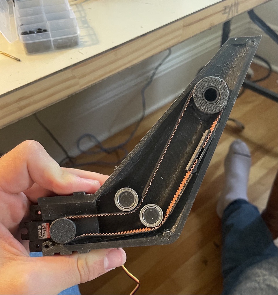
The first iteration of the tail belt assembly used to actuate the rear wing spar. The design routes the belt around the bend in the tail but does not include a tensioning mechanism. During early tests, belt skipping was observed under load, which affected the reliability of wing actuation. In later versions, the design was modified to include a belt tensioner to prevent slippage and improve control accuracy.
Actuating the Wings
The wing spars are rotating in response to an RC command, driven by the servos. The movement confirms that the signal from the receiver is correctly processed and transmitted to the actuators. The rotation is steady and matches the input, showing that the linkage and control system are working as expected. This was an early test to verify basic actuation.
Initial Tuning
The initial tuning was done on a single axis by constraining the drone to one degree of freedom using a carbon fiber rod placed between two wooden blocks. This setup allowed for controlled testing of the pitch axis response to PID inputs. Although the friction from the rod introduced some interference, it served as a useful starting point for establishing baseline PID values. Despite its limitations, the test provided valuable insight into the system’s dynamic behavior.
Tuning on a Universal Joint
After completing the roll axis tuning, we transitioned to tuning the control loops using a universal socket wrench joint to allow for more realistic multi-axis movement. This setup provided greater freedom of motion while still keeping the system constrained enough for safe testing. Through repeated adjustments to the PID values, the system gradually became more stable and responsive. The final tuning results show that it can now handle significant external disturbances without losing control.
Lessons Learned
The goal was to combine the maneuverability and stability of a quadrotor with the efficiency of fixed-wing flight. The design is novel, but it proved infeasible within the given time frame. I underestimated the difficulty of active stabilization and learned the importance of integrating passive stability into aircraft design. The motors were not able to generate enough torque to vector thrust quickly enough to dampen oscillations during the transition from quadcopter to fixed-wing flight. Although we failed to achieve this goal in the time frame, we were able to maintain stable quadcopter flight and accurate wing actuation and positioning.