Project
Canadian UAS Competition
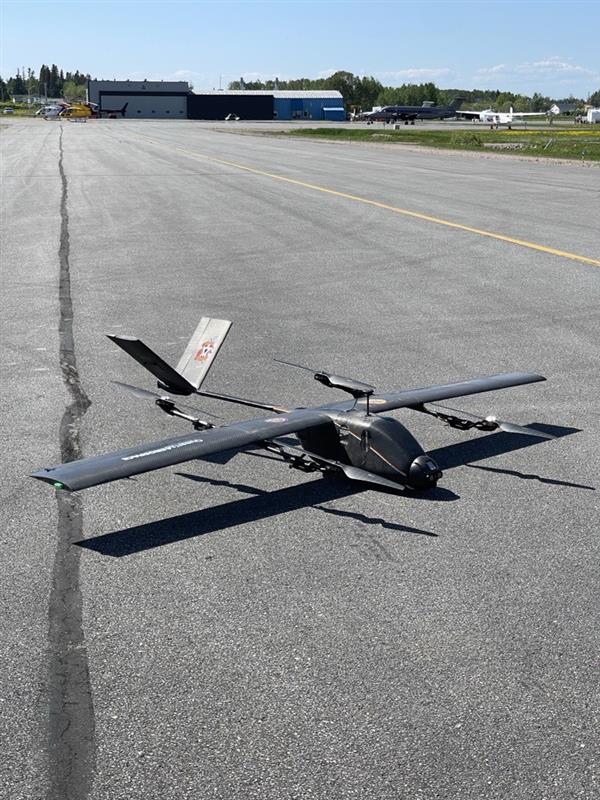
A Complete Aircraft
A look at the fully assembled aircraft, showcasing the completed airframe with wings attached and all internal components integrated. The design features a sleek, aerodynamic profile with the carbon fiber skin providing both strength and weight savings. The aircraft is now ready for final system checks and flight testing, marking a significant milestone in the project.
First Conceptual Design
This graphic was created by William Conway for the team’s first conceptual design review. The outer mold line was developed by the aerodynamics team, led by Will, as part of the initial airframe shaping process. The design required close cross-discipline collaboration, with input from avionics, power systems, and structures to determine component placement and weight distribution.
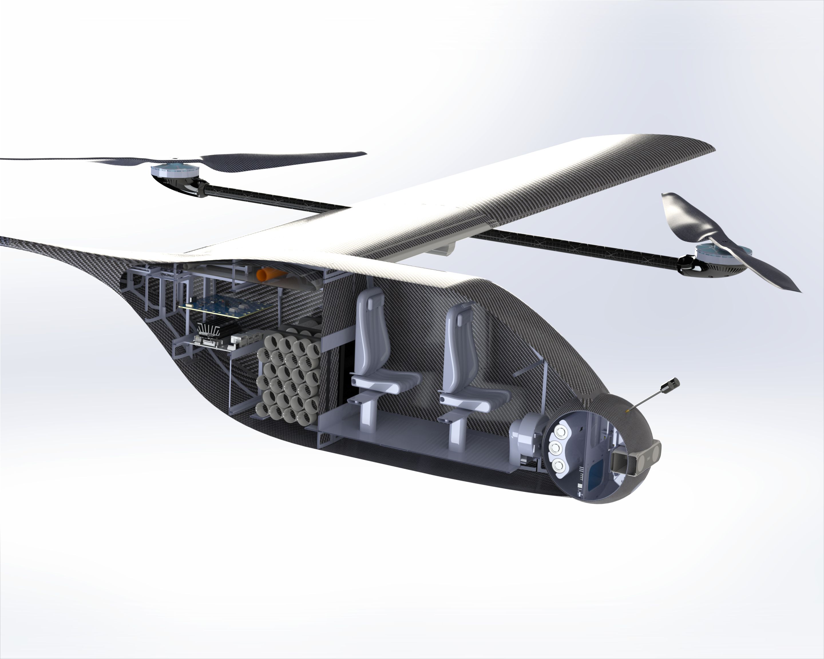
Urban Transport
I created this graphic at the end of the project to clearly illustrate the design layout and overall purpose of the aircraft. It highlights the placement of key components, including the battery pack, power distribution board, onboard computer, gimbal, and passenger cabin. The visual helps communicate how each subsystem fits within the airframe and supports the mission objectives. It also reinforces the core intent of the competition, simulating the real-world challenges of urban air mobility and autonomous passenger transport.
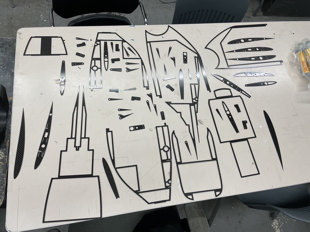
The Build
Mateo Schwartz-Mendez designed a clever interlocking carbon fiber internal structure that formed the backbone of the airframe. This structure provided strength, rigidity, and precise alignment for component mounting while keeping weight low. The first phase of the build process began with the cutting of these parts on a water jet, marking the transition from design to fabrication.
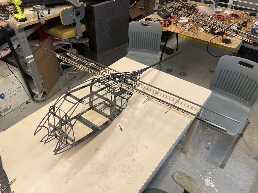
Internal Assembly
The beauty of this design is clearly shown in this picture: none of the pieces are glued in place yet, as the entire structure is held together through precise friction fits. The interlocking geometry allows the parts to self-align and hold their shape even before adhesive is applied. This not only highlights the precision of the water-jet cutting and design work but also makes the gluing process much easier and more accurate. It's a great example of smart structural design simplifying assembly.
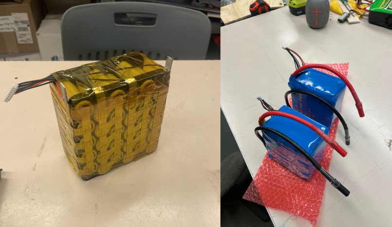
6S 5P Li-ion Battery Pack
In parallel with the mechanical assembly, the electrical system was being developed and became my main technical responsibility after our dedicated electrical lead stepped away from the team for personal reasons. My first task was designing the lithium-ion battery packs, which we chose for their superior energy density compared to LiPo alternatives. I spot-welded two 6-cell, 5-parallel (6S5P) battery packs, carefully assembling them to meet our endurance and power requirements. We opted not to include an onboard battery management system (BMS) due to weight and cost constraints. Instead, balance leads were soldered to each cell group for external monitoring and balancing. In hindsight, using a BMS on the charging end could have streamlined our workflow during competition by enabling faster, safer charging without needing to remove the batteries.
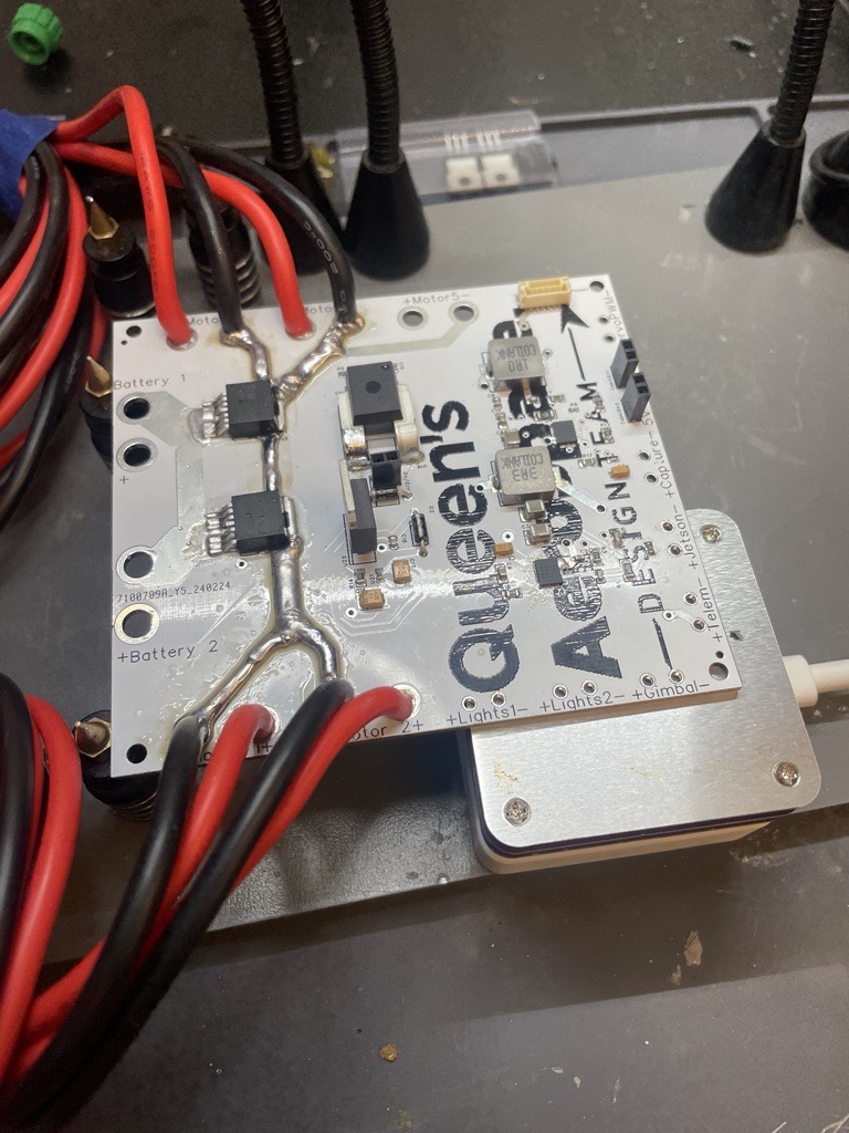
Power Distribution Board
The power distribution board was my first-ever PCB design, and as a result, it had several shortcomings. The board was intended to manage system power, monitor voltage and current, and supply 12V and 5V rails via buck converters rated for 10A and 5A output, respectively. However, the buck converters underperformed under load, likely due to excessive loop lengths and not following the datasheet’s recommended layout closely enough. The current sensor also failed to integrate properly with the flight control firmware as intended. After designing a similar board for a separate project, I’ve since learned that the necessary firmware modifications are relatively straightforward. Despite these issues, many parts of the board functioned well, including the low-side N-channel MOSFET switching, which proved to be a useful and reliable feature.
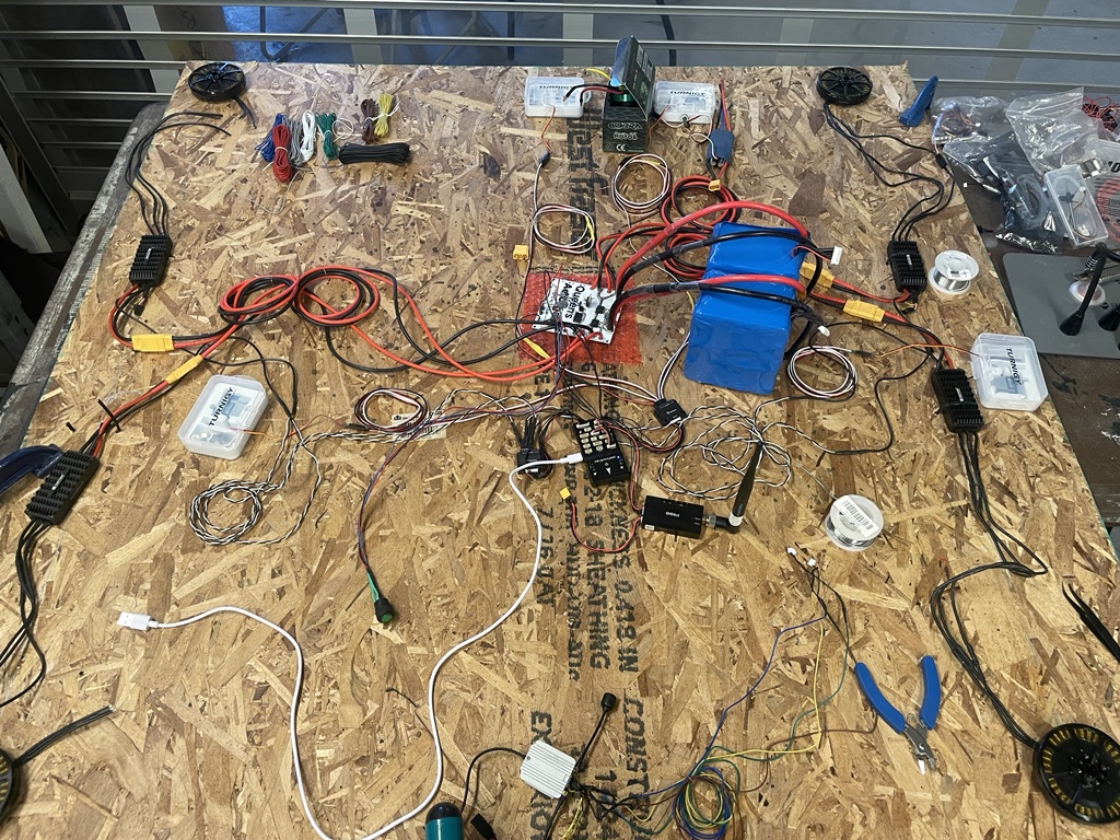
Iron Bird Testing
I then wired the full electrical system onto a piece of plywood to create an 'iron bird' test setup. This approach is commonly used to verify that power distribution, control surfaces, the flight control unit (FCU), and all connected peripherals function correctly before integration into the airframe. It also allows for testing the system under realistic load conditions to confirm stable operation. This step was critical for catching wiring or configuration issues early in a controlled environment.
Internal Wiring
This image shows the internal electrical system being added to the mechanical assembly for a test fit. The goal was to verify cable lengths, connector alignment with external panels, and overall layout before final integration. Since much of the wiring and power distribution needed to be in place before gluing the carbon fiber skin over the internal structure, this step was critical. Full system testing at this stage ensured that everything would be accessible and functional after final assembly.
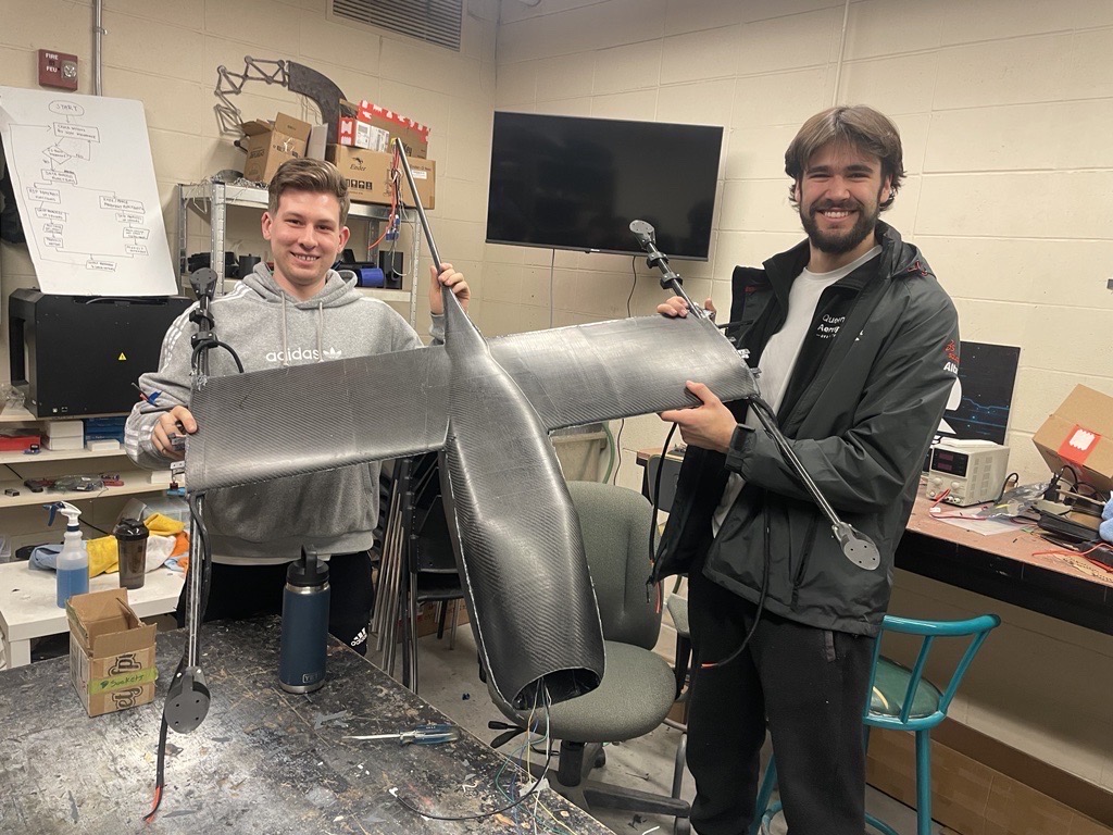
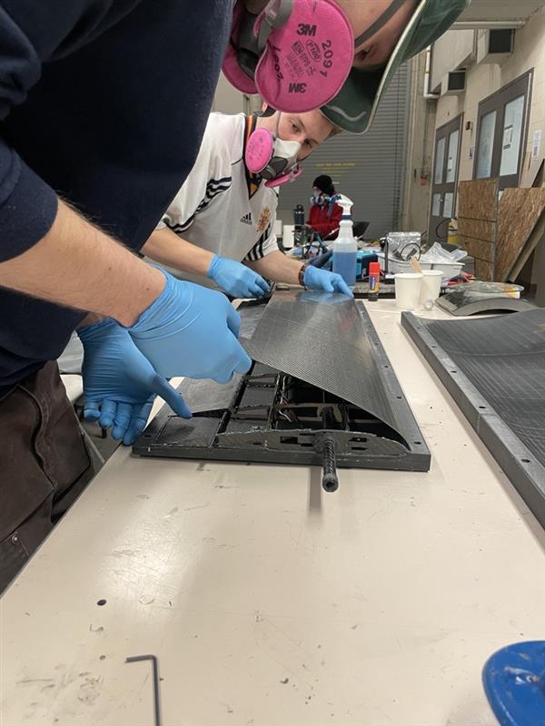
Semi-Monocoque Fuselage
The mechanical team, led by Mateo, chose a semi-monocoque design to significantly increase the structural rigidity of the airframe. While effective, the gluing process for this design proved to be extremely challenging. The epoxy had a one-hour set time, and both the internal structure and carbon fiber skin had to be glued in a single attempt to ensure proper alignment. To achieve this, all components were clamped together using the same molds that had been used for the carbon fiber layups.
Wing Assembly
The wings were assembled using a similar process, built around two large carbon fiber wing spars and laser-cut wooden ribs for structural support. Telemetry and airspeed sensor cables were routed through the internal structure during assembly and glued into place to ensure secure and clean integration. This approach allowed the wings to maintain a lightweight yet rigid construction. Careful planning was required to ensure all internal components were positioned correctly before final bonding.
Initial Flight Test
Initially, we conducted flight tests without the wings to validate the flight control system and ensure stable operation. This approach allowed us to focus on tuning the quadcopter's flight characteristics without the added complexity of wing aerodynamics. The test was successful, demonstrating that the core flight control algorithms were functioning as intended and that the aircraft could maintain stable hover and controlled flight.
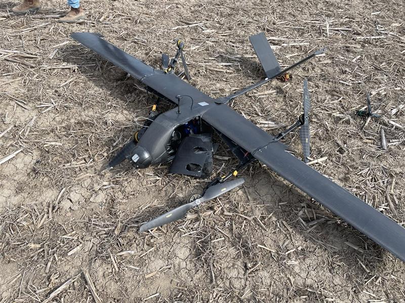
Maiden Flight Crash
This picture shows the damage sustained during our first transition test, which ended in a significant crash. The failure was caused by strong gusts that introduced external disturbances, ultimately leading to a stall mid-transition. In hindsight, we should not have flown that day because wind conditions were unfavorable, but the pressure of limited testing time before team members left for the summer influenced the decision. The combination of a tight timeline and fatigue led to poor judgment on my part, and it’s a mistake I’ve taken seriously and will not repeat.
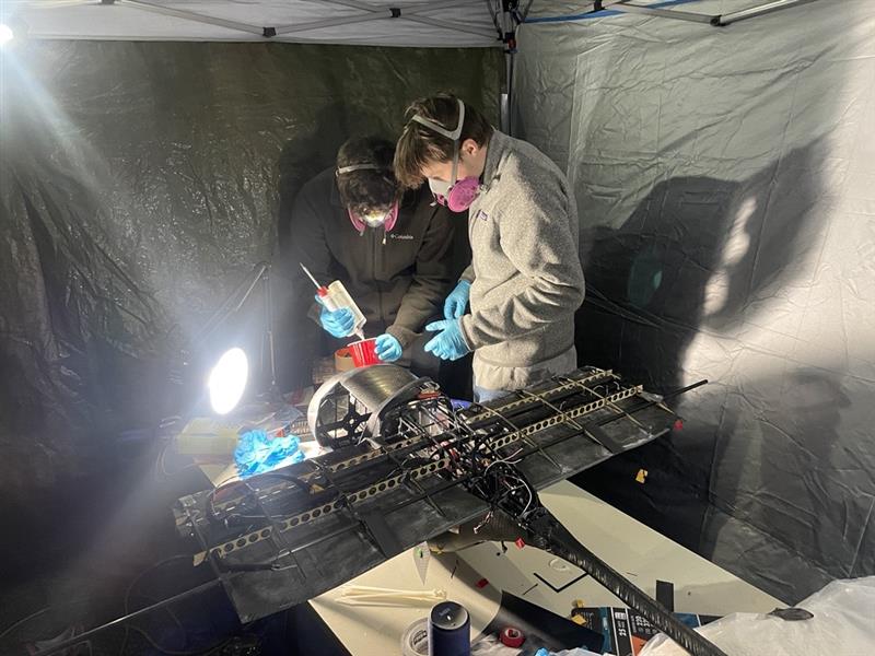
Sleepless Repair
After the crash, extensive repairs were required in the weeks leading up to the competition to salvage the work we had put in over the year. One of our team members, Sam Williamson, stayed at my house during this period to help with the rebuild. The process involved many late nights, as we worked to restore the aircraft while also managing full-time job commitments. The resulting sleep deprivation was intense and unlike anything I had experienced before, but it was a necessary push to get the project flight-ready in time.
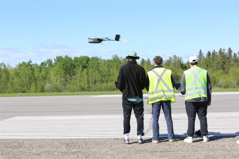
Post-Crash Testing
This video captures a flight test conducted in Nova Scotia following the crash and subsequent repair efforts. It shows the aircraft back in the air, successfully completing basic maneuvers and demonstrating that critical systems, flight control, power distribution, and structural integrity had been restored. The flight marked a major milestone in confirming the effectiveness of the repairs made under tight time and resource constraints. It was a reassuring moment for the team, proving that the project could still move forward despite the earlier setback.
Competition Day
The competition was an incredible experience, offering the chance to see how other teams approached the same problem with different design philosophies and technical strategies. It was both humbling and inspiring to observe the ingenuity, as well as the surprising similarities, across various solutions. Being surrounded by like-minded individuals who shared a passion for UAV design and problem-solving created a collaborative and motivating atmosphere.
Lessons Learned
This project taught me the importance of sound judgment under pressure. Rushing flight tests in poor weather due to time constraints led to avoidable failure. It reinforced the value of thorough pre-integration testing, like iron bird setups and load testing, which help catch critical issues before final assembly. Working on my first PCB highlighted how essential good layout practices and serviceability features are, especially for power systems. I also learned that simulation alone is not enough; many issues only become apparent during physical testing. Above all, the experience underscored the importance of collaboration, as the project could not have been salvaged without the dedication and support of teammates during intense repair efforts.
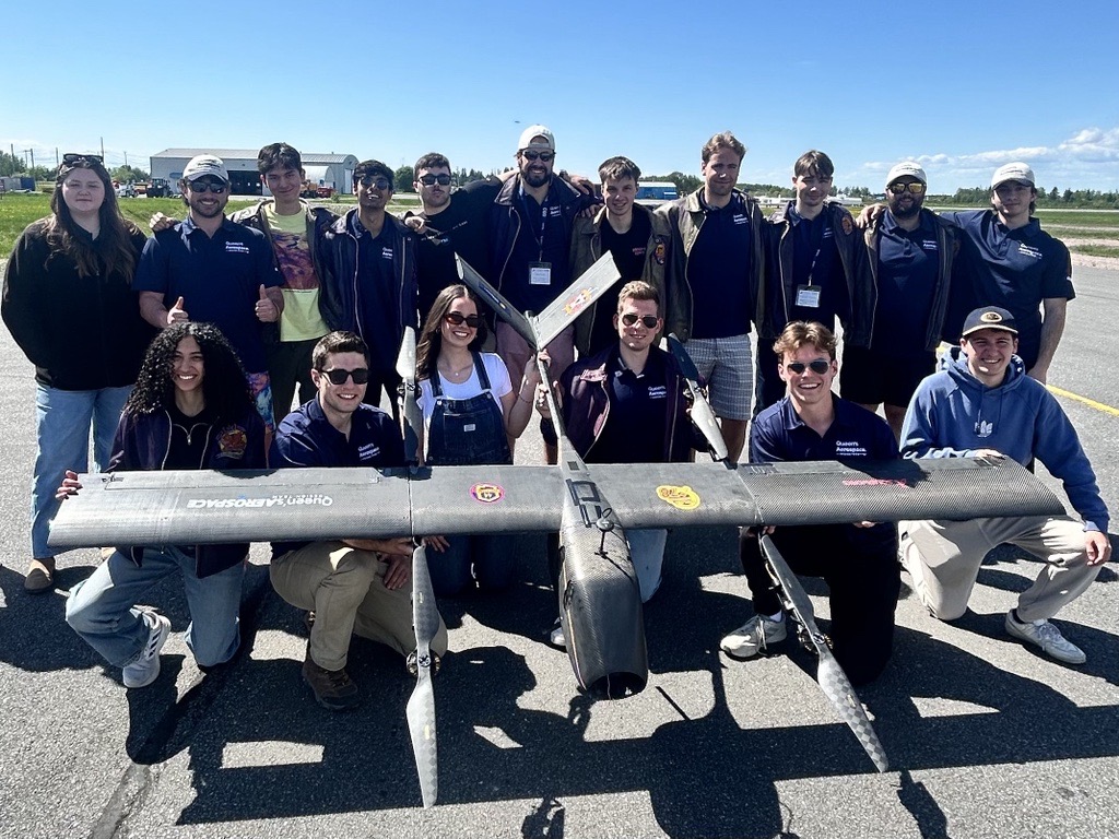
Dream Team
It is important to recognize how much of a team project this was. Without this group of amazing engineering students, none of this would have been possible. Although everyone had a defined role, cross-discipline collaboration was key to our success. I am sharing our process and results here to highlight the work we did together. It is hard to put into words the number of hours and amount of effort this team put into the project, but I am proud to have been a part of it. More about the team members can be found below.